802.1X uses the EAP to authenticate users who wish to access the network.
EAP messages are exchanged between a supplicant and an authenticator, which are tunneled inside the EAPOL and RADIUS protocols
EAP introduces the philosophy that the supplicant should talk directly to the authentication server, with all intermediate devices acting only as relays
Tunnel and Non-Tunnel EAP
Supplicant sends its identity (name) in the clear to the authentication server. This is followed by an exchange that authenticates the authentication server to the user, and the user to the authentication server.
limitation of transmitting the user identity (but not the credentials) in the clear
Transmitting the challenge-response authentication exchange in the clear can facilitate some passive dictionary attacks, if user passwords are weak
To overcome these limitations, you can use a tunneled EAP architecture, in which an outer EAP encapsulates an inner EAP.
The outer EAP provides server authentication, and a cryptographically secure tunnel for the inner EAP method to run in.
Typical outer EAPs are PEAP and EAP-FAST. EAP-MSCHAPv2, EAP-TLS and EAP-GTC are commonly used for the inner EAP.
Wednesday, August 7, 2019
MAC Authentication Bypass
When the MAB feature is enabled on an 802.1X port, the authenticator uses the MAC address as the client identity.
The authentication server has a database of client MAC addresses that are allowed to access the network.
After detecting a client on an 802.1X port, the authenticator waits for an Ethernet frame from the client.
The authenticator sends an Access-Request message using the MAC address of the endpoint as both the username and the password to the RADIUS server.
The RADIUS server can then compare the MAC address against entries in its policy database to make authorization decisions.
If an EAPOL packet is detected on the interface during the lifetime of the link, the authenticator determines that the device connected to that interface is an 802.1X-capable supplicant and uses 802.1X authentication (not MAB) to authorize the interface
The authentication server has a database of client MAC addresses that are allowed to access the network.
After detecting a client on an 802.1X port, the authenticator waits for an Ethernet frame from the client.
The authenticator sends an Access-Request message using the MAC address of the endpoint as both the username and the password to the RADIUS server.
The RADIUS server can then compare the MAC address against entries in its policy database to make authorization decisions.
If an EAPOL packet is detected on the interface during the lifetime of the link, the authenticator determines that the device connected to that interface is an 802.1X-capable supplicant and uses 802.1X authentication (not MAB) to authorize the interface
- A method to allow exemptions from 802.1X authentication
- Certain MAC addresses skip the regular authentication process
- MAC address sent in RADIUS Access-Request message
- Exempted MAC addresses defined as endpoints on the server
802.1X Phased Deployment Guidelines
802.1X can be implemented using a phased deployment model that allows for limited impact on network access while gradually introducing authentication and authorization.
It is generally recommended to begin the phased deployment with monitor mode in a well defined area of the network.
Think of this phase as an audit phase. Your network administrators can gain visibility into who will succeed and who will fail, determine the failure reason, and remediate the problem before enabling a stronger enforcement mode.
It is generally recommended to begin the phased deployment with monitor mode in a well defined area of the network.
Think of this phase as an audit phase. Your network administrators can gain visibility into who will succeed and who will fail, determine the failure reason, and remediate the problem before enabling a stronger enforcement mode.
Before moving from monitor mode to a stronger enforcement mode, you must decide whether low impact mode or closed mode is most appropriate.
The choice will depend on factors internal to your organization and your organization's security policy. It is possible that different modes may be appropriate in different areas of your network. For example it may be optimal to use low impact mode at the headquarters campus and closed mode at branch offices.
After a successful phase of deployment, it is time to move to the next phase.
After a successful audit phase, you can move to the preferred enforcement mode for that area of the network.
You can also extend the identity solution to other areas of the network using monitor mode.
After a successful audit phase, you can move to the preferred enforcement mode for that area of the network.
You can also extend the identity solution to other areas of the network using monitor mode.
802.1X Closed Mode
The default behavior on a Cisco switch port configured for 802.1X is closed mode.
With closed mode, no traffic allowed only EAPOL traffic is allowed until the authentication process completes.
Authentication is required before any basic network services are available, including DHCP. Consideration of 802.1X timers is very important with closed mode
When a device connected to that switch port authenticates, an appropriate authorization policy can be applied. Options for authorization policies include downloadable ACLs, dynamic VLAN assignment or security group tags.
Note: NO authentication open or ip access-group default-ACL in
With closed mode, no traffic allowed only EAPOL traffic is allowed until the authentication process completes.
Authentication is required before any basic network services are available, including DHCP. Consideration of 802.1X timers is very important with closed mode
When a device connected to that switch port authenticates, an appropriate authorization policy can be applied. Options for authorization policies include downloadable ACLs, dynamic VLAN assignment or security group tags.
Note: NO authentication open or ip access-group default-ACL in
interface GigabitEthernet 0/1 authentication host-mode multi-auth authentication port-control auto mab dot1x pae authenticator
802.1X Low-Impact Mode
With low-impact mode, you are able to strengthen the security stance by adding an ingress ACL to the 802.1X-enabled switch port that is configured in open mode. This ACL provides the ability to maintain whatever basic connectivity is required for unauthenticated hosts.
This procedure can be used to provide a host that is attached to a default port with the ability to use DHCP, DNS, and perhaps get to the Internet, while blocking access to internal resources.
When a device connected to that switch port authenticates, an appropriate authorization policy can be applied. Options for authorization policies include downloadable ACLs, dynamic VLAN assignment or security group tags.
- Limited, basic access prior to authentication
- Port ACL applied to the switch interface
- Default port ACL, if no interface ACL exists
- Grant specific access after successful authentication
- dACL received from server
interface GigabitEthernet 0/1 authentication host-mode multi-auth authentication open authentication port-control auto mab dot1x pae authenticator ip access-group default-ACL in
802.1x monitor mode
- Monitor mode is enabled using 802.1X with the open access and multiauth mode Cisco IOS Software features.
- Monitor mode is configured with the
authentication opencommand. - The default behavior of 802.1X is to block all data traffic except EAPOL. However, the open access feature allows you the option of providing unrestricted access to all traffic, even though authentication (802.1X, MAB, or web authorization) is enabled. Open access is accomplished with no impact to end users or network-attached hosts.
- Even failed authentication will allow access
- Network administrators can:
- See who would have failed
- Resolve the problem before causing a Denial of Service
- No effect on user or endpoint access
- AAA RADIUS accounting provides visibility into 802.1X operation
interface GigabitEthernet0/1 authentication host-mode multi-auth authentication open authentication port-control auto mab dot1x pae authenticator
802.1X Phased Deployment
802.1X can be implemented using a phased deployment model that allows for limited impact on network access while gradually introducing authentication and authorization.
- Phased approach for 802.1x deployment
- Gradual authorization enforcement
- Visibility into who will succeed and who will fail
- Determine the failure reason
- Remediate before implementing stronger enforcement
- Modes:
- Monitor mode
- Low impact mode
- Closed mode
- This figure summarizes the preauthentication and post-authentication behavior of the three 802.1X deployment phases: monitor, low-impact, and closed modes.
- In monitor mode, the open access feature transforms the normal behavior of blocking traffic on an 802.1X-enabled port until authentication and authorization are successfully performed. Full access is provided independently of the authentication results.In low-impact mode, a pre-authentication ACL is added to the port to permit some basic connectivity. After successful authentication, options to enforce authorization policy include downloadable ACLs, dynamic VLAN assignment and security group tags.In closed mode, only EAPOL traffic is permitted until the user authenticates. After successful authentication, options to enforce authorization policy include downloadable ACLs, dynamic VLAN assignment and security group tags. The authorization options available in closed mode are identical to the options available in low-impact mode.
802.1X host modes.
802.1X host modes.
- Single Host mode:
- Only one device (MAC address) per port
- Second client causes unauthorized port state
- Multiple Host mode:
- One device (first MAC address) authenticated
- All subsequent devices get access
- MDA mode:
- One data and one voice VLAN per port
- Independent authentication of phone and PC
- Multiple Authentication mode:
- Superset of MDA
- Authenticates every MAC address
- One VLAN for all devices, per device dACL
- Used for hubs, access points, Virtual Machines
The host mode of the 802.1X port determines whether more than one client can be authenticated on the port and how authentication will be enforced. You can configure an 802.1X port to use any of the four host modes that are described below. In addition, each mode may be modified to allow pre-authentication open access.
Single-Host Mode
In single-host mode, only one client can be connected to the 802.1X-enabled port. The switch detects the client when the port changes to the up state and sends out an EAPOL frame. Access is provided for the client after authentication. Packets from other hosts are dropped. If the client leaves or is replaced with another client, the switch changes the port link state to down, and the port returns to the unauthorized state.
Multiple Host Mode
In multiple host mode (often called multi-host mode), you can attach multiple hosts to a single 802.1X-enabled port. In this mode, only one of the attached clients must be authorized for all clients to be granted network access. If the port becomes unauthorized (reauthentication fails or an EAPOL logoff message is received), the authenticator denies network access to all of the attached clients.
Multiple Domain Authentication Mode
MDA mode (often called multi-domain mode) allows an IP phone and a single host behind the IP phone to authenticate independently, using 802.1X, MAB, or (for the host only) web-based authentication. In this application, multidomain refers to two domains (data and voice VLAN), and only one MAC address is allowed per domain. The switch can place the host in the data VLAN and the IP phone in the voice VLAN, but they appear on the same switch port. The data and voice VLAN assignment can be obtained from the VSAs received from the AAA server.
Multiple Authentication Mode
Multiple authentication mode (often called multi-auth mode) allows one 802.1X or MAB client on the voice VLAN and multiple authenticated 802.1X, MAB, or web authorization clients on the data VLAN. When a hub or access point is connected to an 802.1X port, multi-auth mode provides enhanced security over the multi-host mode by requiring authentication of each connected client. For non-802.1X devices, MAB or web-based authentication can be used as the fallback method for individual host authentications, which allows different hosts to be authenticated through different methods on a single port.
In this mode, the first host that is authorized on the port defines the VLAN assignment, and subsequent hosts will be added to the same VLAN. They may either have no VLAN assignment in the RADIUS database, or their configured group VLAN must match the assigned group VLAN on the port. Otherwise they will be denied access to the port.
Also, if the Authentication Server assigns a dACL, the dACL will be modified to use the authenticated host’s IP address as the source address. That is, in multi-auth mode, per-host differentiated dACLs are supported.
Tuesday, November 10, 2015
Universal Power Over Ethernet
UPOE Architecture
As defined in IEEE 802.3af and IEEE 802.3at, PoE delivers electrical power over two pairs out of the four twisted pairs of cable in Class D (also known as Cat5e) or better, cabling as specified in ISO/IEC 11801:1995. A PSE uses only signal pairs, the pairs 1, 2 and 3, 6, to transport power from the PSE to the PD and leaves the spare pairs, the pairs 4, 5 and 7, 8, idle. This architecture can deliver up to 30W per port. (Refer to Figure 5.)
Figure 5. PoE and PoE+ Architecture
UPOE uses the same cabling standard as PoE. Instead of delivering power over two twisted pairs, it provides the capability to source up to 60W of power by using all the four pairs of standard Ethernet cabling (Cat5e or better).
The architecture for a 4-pair system is pretty straightforward; it is an extension of the 2-pair design. The 2-pair system uses one PSE controller to power the PD through the signal pairs of the cable. In the new 4-pair system two PSE controllers will be used to power both the signal pairs and the spare pairs. Figure 6 shows the UPOE architecture.
Figure 6. UPoE Architecture
Table 1 summarizes the primary comparison between PoE, PoE Plus, and UPOE.
Table 1. PoE/PoE Plus/UPOE comparison
PoE
|
PoE Plus
|
UPOE
| |
Minimum cable type
|
Cat5e
|
Cat5e
|
Cat5e
|
IEEE standard definition
|
802.3af
|
802.3at
|
Cisco proprietary
|
Maximum power per PSE port
|
15.4W
|
30W
|
60W
|
Maximum power to PD
|
12.95W
|
25.5W
|
51W
|
Twisted pair used
|
2-pair
|
2-pair
|
4-pair
|
UPOE Operation
This section describes the UPOE operation steps to detect, classify, and negotiate power and subsequently power up the PD.
PD Detection, Classification
The hardware detection and classification mechanism for UPOE follows the IEEE 802.3 standard. The PSE and the PD use a set of physical layer mechanisms to detect the connection of the endpoint and subsequently classify the endpoints into different categories that map to different levels of power requirements. Table 3 lists the PoE classes.
Table 3. PoE Classes
Class
|
Usage of class
|
Minimum Power Levels Output at the PSE
|
Maximum Power Levels at the Powered Device
|
Class description
|
0
|
Default
|
15.4W
|
0.44 to 12.95W
|
Classification unimplemented
|
1
|
Optional
|
4.0W
|
0.44 to 3.84W
|
Very Low Power
|
2
|
Optional
|
7.0W
|
3.84 to 6.49W
|
Low Power
|
3
|
Optional
|
15.4W
|
6.49 to 12.95W
|
Mid Power
|
4
4
|
Reserved in 802.3af
802.3at
|
Treat as Class 0
30W
|
12.95W to 25.5W
|
High Power
|
At power-on, a UPOE device is treated as a PoE device and allocated 15.4W as the default power. After power-on the PSE and PD go through a power negotiation phase to determine exactly how much power will be provisioned from the PSE to the PD.
Friday, October 16, 2015
Proxy ARP
This document explains the concept of proxy Address Resolution Protocol
(ARP). Proxy ARP is the technique in which one host, usually a router,
answers ARP requests intended for another machine. By "faking" its
identity, the router accepts responsibility for routing packets to the
"real" destination. Proxy ARP can help machines on a subnet reach remote
subnets without the need to configure routing or a default gateway.
Proxy ARP is defined in RFC 1027
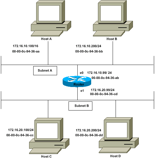
The Host A (172.16.10.100) on Subnet A needs to send packets to Host D (172.16.20.200) on Subnet B. As shown in the diagram, Host A has a /16 subnet mask. What this means is that Host A believes that it is directly connected to all of network 172.16.0.0. When Host A needs to communicate with any devices it believes are directly connected, it sends an ARP request to the destination. Therefore, when Host A needs to send a packet to Host D, Host A believes that Host D is directly connected, so it sends an ARP request to Host D.
In order to reach Host D (172.16.20.200), Host A needs the MAC address of Host D.
Therefore, Host A broadcasts an ARP request on Subnet A, as shown:
In this ARP request, Host A (172.16.10.100) requests that Host D
(172.16.20.200) send its MAC address. The ARP request packet is then
encapsulated in an Ethernet frame with the MAC address of Host A as the
source address and a broadcast (FFFF.FFFF.FFFF) as the destination
address. Since the ARP request is a broadcast, it reaches all the nodes
in the Subnet A, which includes the e0 interface of the router, but does
not reach Host D. The broadcast does not reach Host D because routers,
by default, do not forward broadcasts.
Since the router knows that the target address (172.16.20.200) is on another subnet and can reach Host D, it replies with its own MAC address to Host A.
This is the Proxy ARP reply that the router sends to Host A. The
proxy ARP reply packet is encapsulated in an Ethernet frame with MAC
address of the router as the source address and the MAC address of Host A
as the destination address. The ARP replies are always unicast to the
original requester.
Upon receipt of this ARP reply, Host A updates its ARP table, as shown:
From now on, Host A forwards all the packets that it wants to
reach 172.16.20.200 (Host D) to the MAC address 00-00-0c-94-36-ab
(router). Since the router knows how to reach Host D, the router
forwards the packet to Host D. The ARP cache on the hosts in Subnet A is
populated with the MAC address of the router for all the hosts on
Subnet B. Hence, all packets destined to Subnet B are sent to the
router. The router forwards those packets to the hosts in Subnet B.
The ARP cache of Host A is shown in this table:
Note: Multiple IP addresses are mapped to a single MAC
address, the MAC address of this router, which indicates that proxy ARP
is in use.
The interface of the Cisco must be configured to accept and respond to proxy ARP. This is enabled by default. The no ip proxy-arp command must be configured on the interface of the router connected to the ISP router. Proxy ARP can be disabled on each interface individually with the interface configuration command no ip proxy-arp, as shown:
Note: When Host B (172.16.10.200/24) on Subnet A tries to send packets to destination Host D (172.16.20.200) on Subnet B, it looks into its IP routing table and routes the packet accordingly. Host B (172.16.10.200/24) does not ARP for Host D IP address 172.16.20.200 because it belongs to a different subnet than what is configured on Host B ethernet interface 172.16.20.200/24.
Proxy ARP must be used on the network where IP hosts are not configured with a default gateway or do not have any routing intelligence.
How Does Proxy ARP Work?
This is an example of how proxy ARP works:Network Diagram
The Host A (172.16.10.100) on Subnet A needs to send packets to Host D (172.16.20.200) on Subnet B. As shown in the diagram, Host A has a /16 subnet mask. What this means is that Host A believes that it is directly connected to all of network 172.16.0.0. When Host A needs to communicate with any devices it believes are directly connected, it sends an ARP request to the destination. Therefore, when Host A needs to send a packet to Host D, Host A believes that Host D is directly connected, so it sends an ARP request to Host D.
In order to reach Host D (172.16.20.200), Host A needs the MAC address of Host D.
Therefore, Host A broadcasts an ARP request on Subnet A, as shown:
| Sender's MAC Address | Sender's IP Address | Target MAC Address | Target IP Address |
|---|---|---|---|
| 00-00-0c-94-36-aa | 172.16.10.100 | 00-00-00-00-00-00 | 172.16.20.200 |
Since the router knows that the target address (172.16.20.200) is on another subnet and can reach Host D, it replies with its own MAC address to Host A.
| Sender's MAC Address | Sender's IP Address | Target MAC Address | Target IP Address |
|---|---|---|---|
| 00-00-0c-94-36-ab | 172.16.20.200 | 00-00-0c-94-36-aa | 172.16.10.100 |
Upon receipt of this ARP reply, Host A updates its ARP table, as shown:
| IP Address | MAC Address |
|---|---|
| 172.16.20.200 | 00-00-0c-94-36-ab |
The ARP cache of Host A is shown in this table:
| IP Address | MAC Address |
|---|---|
| 172.16.20.200 | 00-00-0c-94-36-ab |
| 172.16.20.100 | 00-00-0c-94-36-ab |
| 172.16.10.99 | 00-00-0c-94-36-ab |
| 172.16.10.200 | 00-00-0c-94-36-bb |
The interface of the Cisco must be configured to accept and respond to proxy ARP. This is enabled by default. The no ip proxy-arp command must be configured on the interface of the router connected to the ISP router. Proxy ARP can be disabled on each interface individually with the interface configuration command no ip proxy-arp, as shown:
In order to enable proxy ARP on an interface, issue the ip proxy-arp interface configuration command.Router# configure terminal Enter configuration commands, one per line. End with CNTL/Z. Router(config)# interface ethernet 0 Router(config-if)# no ip proxy-arp Router(config-if)# ^Z Router#
Note: When Host B (172.16.10.200/24) on Subnet A tries to send packets to destination Host D (172.16.20.200) on Subnet B, it looks into its IP routing table and routes the packet accordingly. Host B (172.16.10.200/24) does not ARP for Host D IP address 172.16.20.200 because it belongs to a different subnet than what is configured on Host B ethernet interface 172.16.20.200/24.
Advantages of Proxy ARP
The main advantage of proxy ARP is that it can be added to a single router on a network and does not disturb the routing tables of the other routers on the network.Proxy ARP must be used on the network where IP hosts are not configured with a default gateway or do not have any routing intelligence.
Disadvantages of Proxy ARP
Hosts have no idea of the physical details of their network and assume it to be a flat network in which they can reach any destination simply by sending an ARP request. But using ARP for everything has disadvantages. These are some of the disadvantages:- It increases the amount of ARP traffic on your segment.
- Hosts need larger ARP tables in order to handle IP-to-MAC address mappings.
- Security can be undermined. A machine can claim to be another in order to intercept packets, an act called "spoofing."
- It does not work for networks that do not use ARP for address resolution.
- It does not generalize to all network topologies. For example, more than one router that connects two physical networks.
Subscribe to:
Posts (Atom)